The Pathway of 0s and 1s
Last episode Ep.0-0, we looked at the big picture: what form visual data takes (bitmaps), how it turns into light (scanning), and how it deceives our eyes (illusions). Today, we will discuss the physical movement of data that occurs between the bitmap and the scanning process.
Imagine this. To fill a standard 4K UHD (3840×2160) monitor running at 144Hz with 10-bit color (HDR), the graphics card needs to fire off about 36 billion bits per second. If just one signal is delayed or mixed up in the narrow cable, the screen breaks or freezes instantly. We often take this incredible speed for granted.
So, how does this vast amount of data move? How did ancient analog waves become precise digital signals? And how does a thin copper wire like an HDMI cable manage such massive traffic?
From the graphics card to your monitor panel, let’s trace this journey.
From Analog to Digital
To understand how data moves, we first need to understand how the nature of data itself has evolved. After all, even the 0s and 1s inside a computer must ultimately transform into physical waves—‘electrical signals’—to travel through a cable.
Let’s look at how we handle these signals: the transition from Analog to Digital.
The Era of Analog
Do you remember? That chunky cable with the blue head, the D-Sub (VGA). In the era ruled by this cable, the CRT (Cathode-Ray Tube) monitor was essentially a giant electron gun.
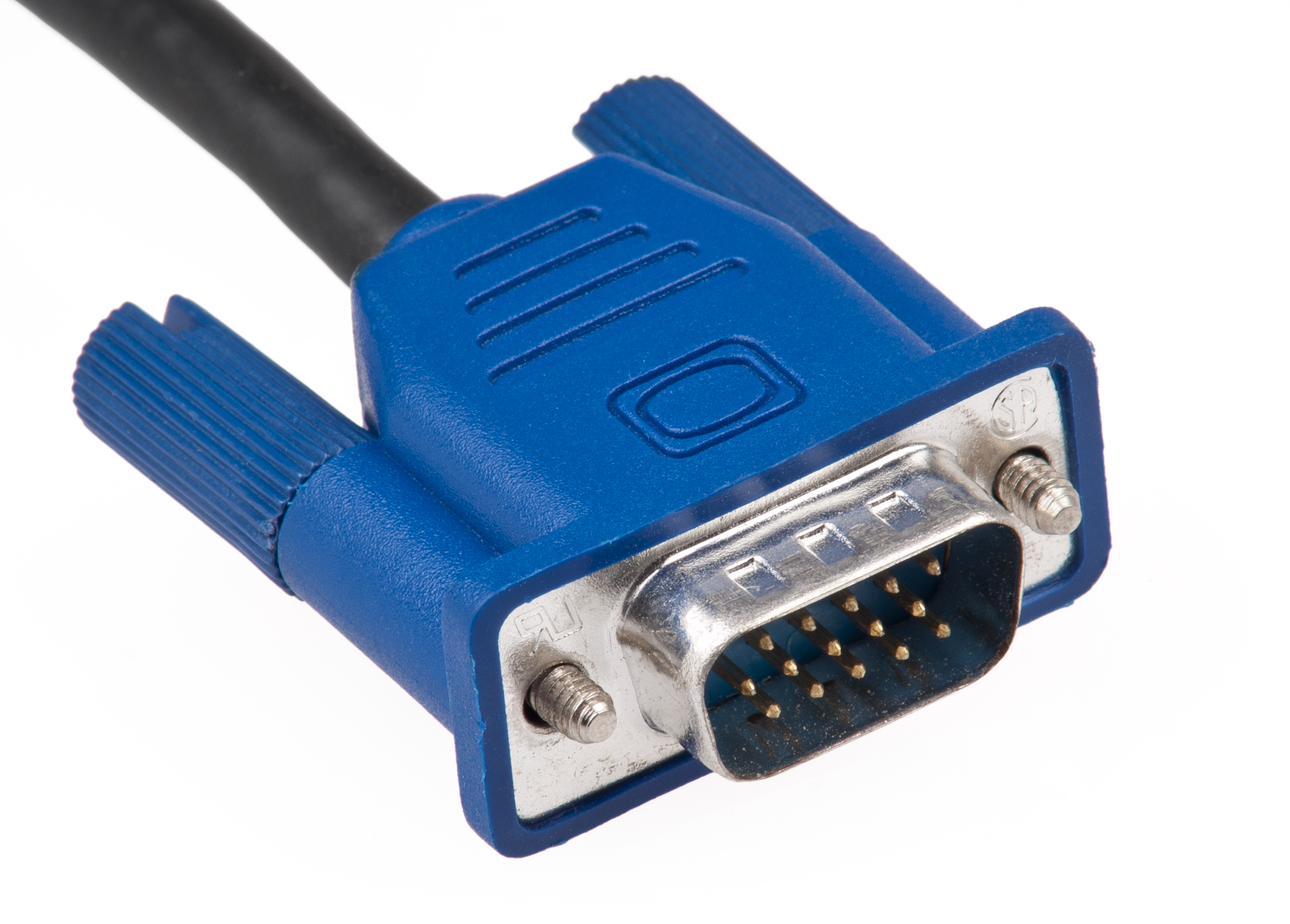 Source: Wikimedia Commons / Evan-Amos
The CRT fired electron beams from the back of the screen, causing the phosphors coated on the front glass to glow as if they were burning. The signal at this time was a continuous wave. It was an intuitive system: increase the voltage to make it brighter, decrease it to make it darker.
There were no physical boundaries known as “pixels” here. Therefore, resolution at that time referred to the density of the signal, not the number of physical grid points. Thanks to this, CRTs could display smooth images at any resolution without becoming blurry.
However, this method had a fatal flaw: external interference. Analog signals were incredibly vulnerable to their environment. If the cable was too long or a magnet was placed nearby, the wave would distort, leading directly to screen noise and color bleeding.
Thus, we needed a more stable and accurate method.
The Digital Revolution
With the advent of LCD monitors, the world shifted to a Grid. The screen was no longer a free-flowing canvas; it became a giant sheet of graph paper, densely packed with millions of tiny light bulbs arranged in rows and columns.
Data was no longer a continuous wave. It became precise numerical values with coordinates (X, Y) and color values (RGB). Converting a continuous world into discrete numbers—this is exactly what we call ‘Quantization’. Thanks to this, digital signals remain unchanged regardless of cable length or external interference. The exact color intended by the graphics card is delivered directly to the monitor.

However, this change came with a price. The amount of data to be transmitted increased explosively. In the analog era, you could simply maintain a voltage level to say, “Draw a line from here to there.” In the digital era, however, you have to command each and every one of the hundreds of dots that make up that line.
In exchange for sharpness and accuracy, we faced the problem of massively increased traffic. To handle this, we needed wider, more robust pathways. Thus began the War of Bandwidth.
The Bandwidth War and the Evolution of Pathways
To handle this massive traffic, the concept of bandwidth emerges.
What is Bandwidth?
It is essentially the width of the pathway through which data travels. The required bandwidth is calculated as follows:
Bandwidth = Resolution (Size of Cargo) * Refresh Rate (Delivery Speed) * Color Depth (Packaging Thickness)
What happens if the cable’s bandwidth is smaller than this pouring traffic? A bottleneck occurs. The screen flickers, the signal cuts out, or in the worst case, nothing shows up at all.
HDMI vs. DP
To create this wide pathway, we primarily use two standards. They look similar but are fundamentally different from birth: HDMI (High Definition Multimedia Interface) and DP (DisplayPort).
| Type | Purpose | Method | Strength |
|---|---|---|---|
| HDMI | Transmits Video + Audio at once | Streaming | Versatility |
| DP | Data integrity and scalability in PC environments | Packet-based | Professionalism |
Physical Constraints: The Limits of Copper and the Salvation of Light
However, no matter how good the pathway is, we cannot avoid the physical constraint of distance.
Most cables are made of copper wire. Here, electrical signals weaken due to resistance. Especially with high-capacity data like 4K or 8K, the signal becomes rapidly unstable if the length exceeds just 2 meters.
To overcome this physical limit, Fiber-optic cable appeared. The principle is simple. The connector head converts the electrical signal into light and shoots it. Light has no electrical resistance. Even after flying tens of meters, there is almost no data loss. When the light reaches the connector on the other side, it is converted back into an electrical signal and enters the monitor. Thanks to this, the monitor can output a pristine image.
The Secret of USB-C
These days, many people connect monitors via USB-C cables. If HDMI and DP are dedicated lanes drilled solely for ‘video’, USB-C is a smart pathway that changes lanes depending on the situation.
Strictly speaking, USB-C is merely the ‘Shape of the Connector’, not a communication standard. The moment you plug a USB-C cable into a monitor, ‘DP Alt Mode’ activates inside. Some of the lanes used for data transmission are immediately repurposed for DP signals. (This is possible because they share the same packet-based method.)

In this way, USB-C can perform various roles such as charging, file transfer, and video transmission. However, this flexibility causes confusion. Cheap charging USB-C cables often lack the video lanes inside entirely. In other words, not all USB-C cables can act as DisplayPort. Don’t forget that you must use a thick cable explicitly marked with specifications like Gen 2, 10Gbps, or 4K support.
What if there is a small lightning bolt symbol on the USB-C port? That fellow is called ‘Thunderbolt’. It is a premium standard created by Intel and Apple. It looks exactly like USB-C, but the speed is in a different dimension. It offers bandwidth 2 to 4 times faster (40Gbps or more) than standard USB-C.
The Panel
Massive amounts of data have traveled through the cable and reached their destination. Now, only one task remains: converting these digital signals into light that our eyes can see. This is the role of the Panel.
LCD (Liquid Crystal Display): Blocking the Light
LCDs cannot emit light on their own. At the very back, a ‘Backlight’ constantly emits white light. In front of it, there are millions of tiny shutters known as ‘Liquid Crystals’, and at the very front, ‘Color Filters’ (Red, Green, Blue) are attached. To create black, you simply close all these shutters; to create white, you open them all wide to let the light pass through.

At this point, LCDs are divided into three main types depending on how the shutters move.
| Type | Method | Characteristics |
|---|---|---|
| IPS | Liquid crystals rotate horizontally in place. | Accurate colors and wide viewing angles, but weaker contrast ratio. |
| TN | Liquid crystals twist. | The fastest response time, but narrow viewing angles. |
| VA | Liquid crystals align vertically. | Great contrast ratio, but ghosting may occur during fast screen transitions. |
OLED (Organic LED): Shining by Itself
Each pixel consists of organic material that emits light on its own.
To express black, it simply cuts off the power to that pixel, achieving perfect darkness. The response speed is also much faster than LCDs because it doesn’t need time to adjust liquid crystals.
However, organic materials have a limited lifespan. Therefore, if a specific pixel is kept bright for too long, a permanent stain may remain on that part. This is the Burn-in phenomenon.
MicroLED is being researched to overcome these limitations of OLED. It uses inorganic materials with almost infinite lifespans instead of organic ones. It is a display free from burn-in, but it is very expensive.
Reference: Surface Coating
No matter how good the panel is, it is useless if the finishing material covering it is poor. This is called ‘Surface Coating’.
-
Glossy: A smooth, glass-like texture. It transmits light directly, making colors vivid and sharp. However, surrounding objects reflect like a mirror, which can easily tire the eyes.
-
Matte (Non-Glare): A texture treated to be rough and non-reflective. It scatters light to prevent reflections. It is comfortable for the eyes, but the screen may look slightly hazy or grainy.
Through the Path, Finally Becoming Light
Today, we explored the long journey of visual data passing through the Cable, and finally reaching the Panel before our eyes.
We covered the evolution into digital signals, the massive bandwidth required to handle that traffic, and the physical structure of the monitor panel that receives these transmitted signals.
But before this transmission happens, who draws all this data, and how? Next time, we set off to find the source of this light. Into the world of the CPU and GPU.